
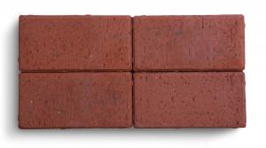
Staffordshire 'Classic' clay pavers
Inherent natural beauty & strength
Crafted to the same exacting standards for over a century, Ketley Staffordshire 'Classic' Clay Pavers are the original benchmark in durability and timeless design. Their rich, distinctive colours—formed naturally in the firing process—are permanent and fade-resistant, offering enduring visual appeal in both heritage and contemporary settings.
Made from premium Etruria marl and fired at temperatures exceeding 1130°C, Ketley Pavers deliver exceptional strength and resilience. Engineered to withstand channelised traffic flow, they are ideal for public realm projects, pedestrianised zones, and areas requiring long-term performance.
The Classic Range reflects traditional british size formats, with a full suite of coordinating specials and fittings available to support complex layouts and bespoke detailing.
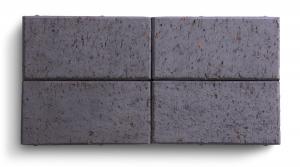
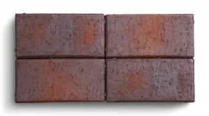
Square edged
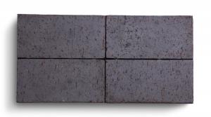
Staffordshire blue
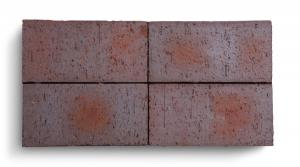
Brown brindle
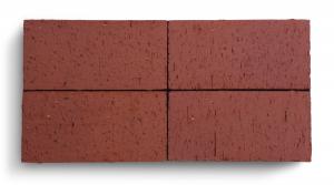
Staffordshire red

New Brown antique
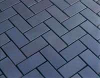
Chamfered
These pavers have chamfered edges rather than sharp edges, an aesthetic that accentuates the joint and laying pattern.
Staffordshire blue
Brown brindle
Staffordshire red
Case Studies
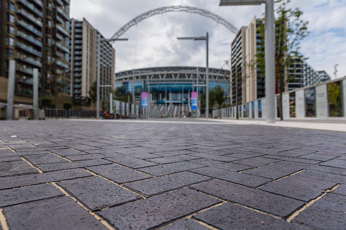
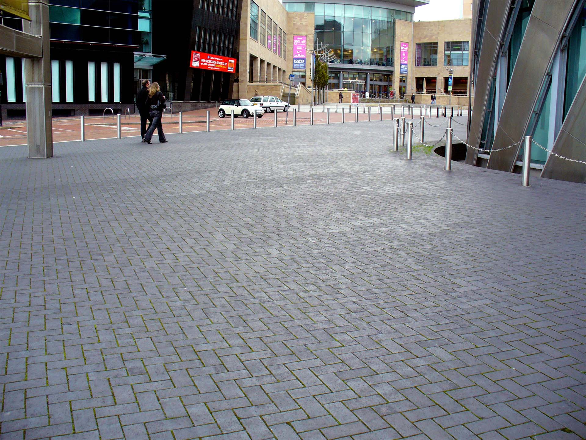
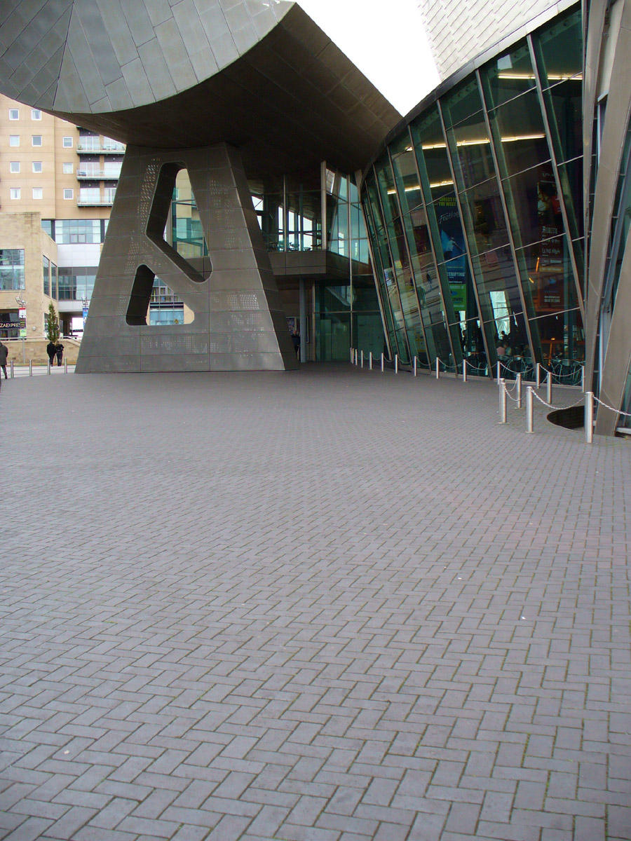
Wembley Way
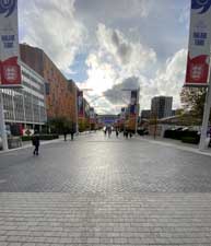
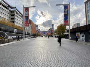
The iconic approach to Wembley Stadium, known as Olympic Way or Wembley Way has undergone a recent transformation in a joint project by Brent Countil and Quintain Estates. The new scheme designed by Dixon Jones Architects has drawn on the heritage of the site, and uses over 200,000 Ketley Staffordshire blue 'Classic' chamfered pavers, laid in a herringbone pattern and interspersed with bands of granite. Full details
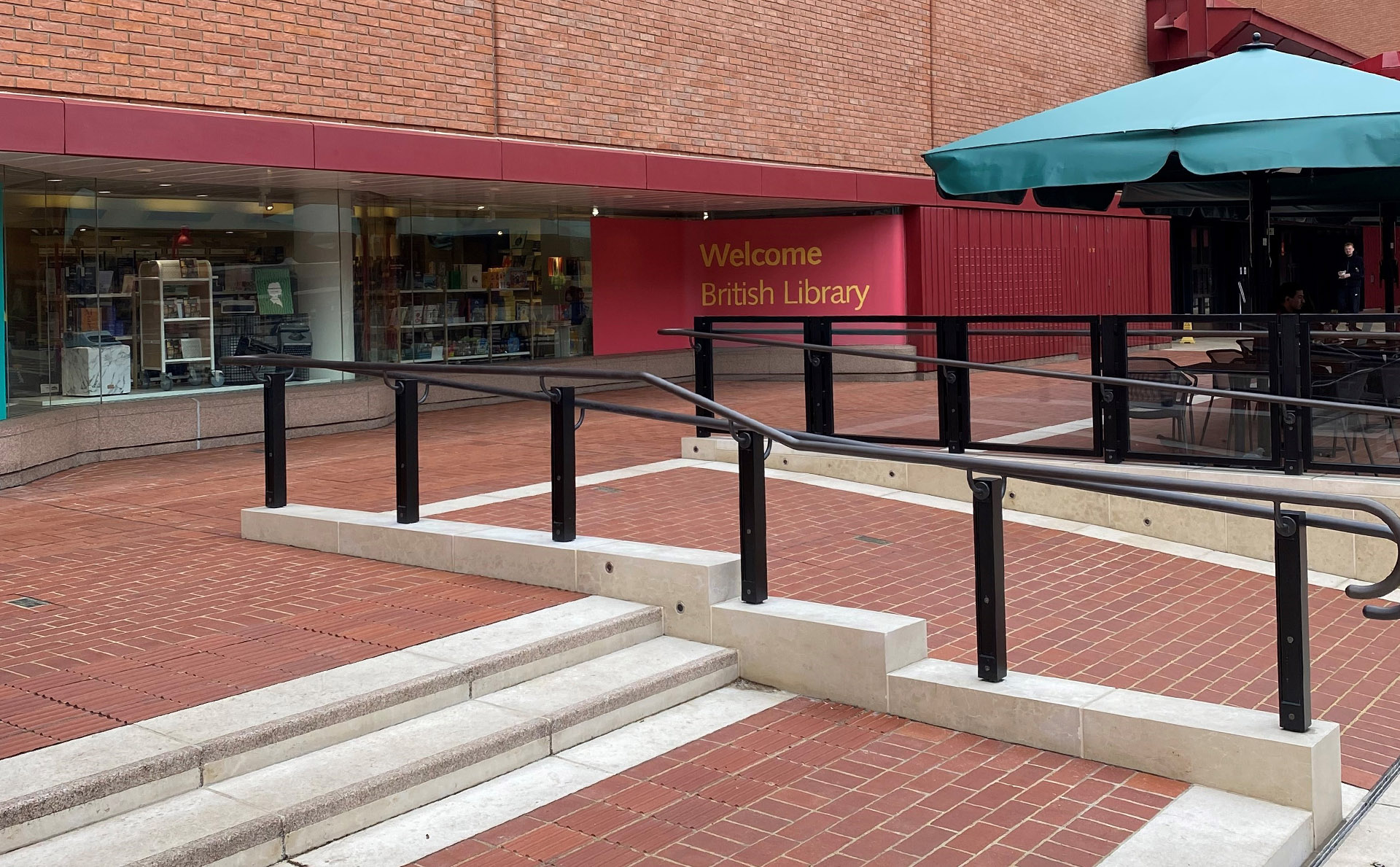
British Library Piazza
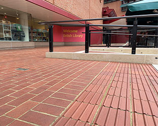
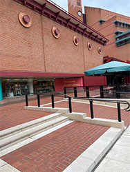
Ketley Staffordshire red 'Classic' square edged and tactile pavers have been used for recent improvement works to the entrance of the iconic Grade I listed British Library. The project required a large number of bespoke plain paver sizes as well as a number of bespoke corduroy tactile pavers to tie it in seamlessly to the existing paved area. Full details
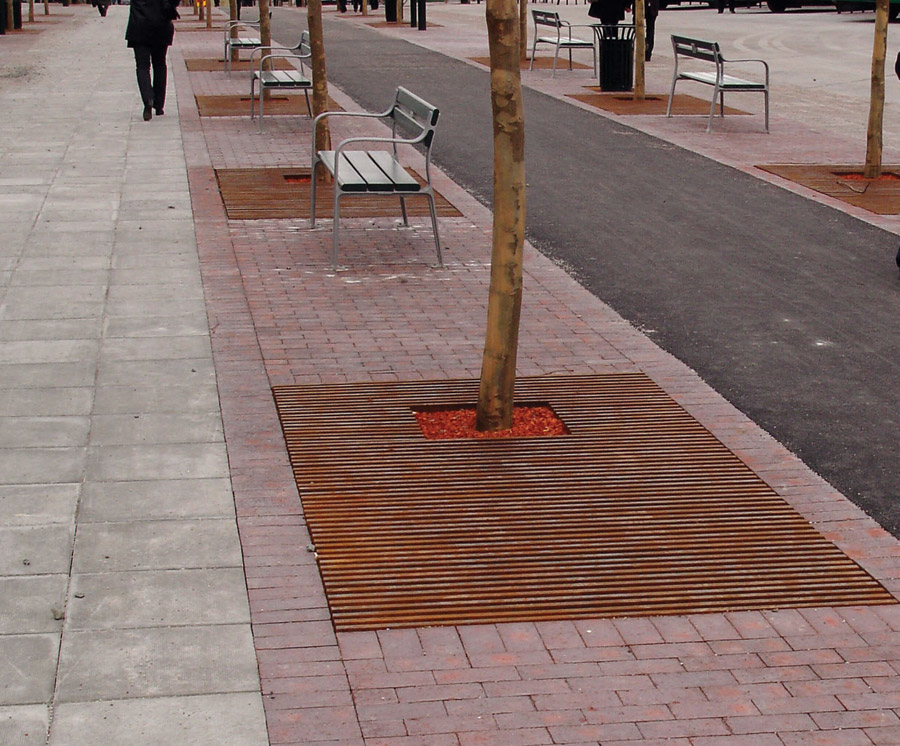
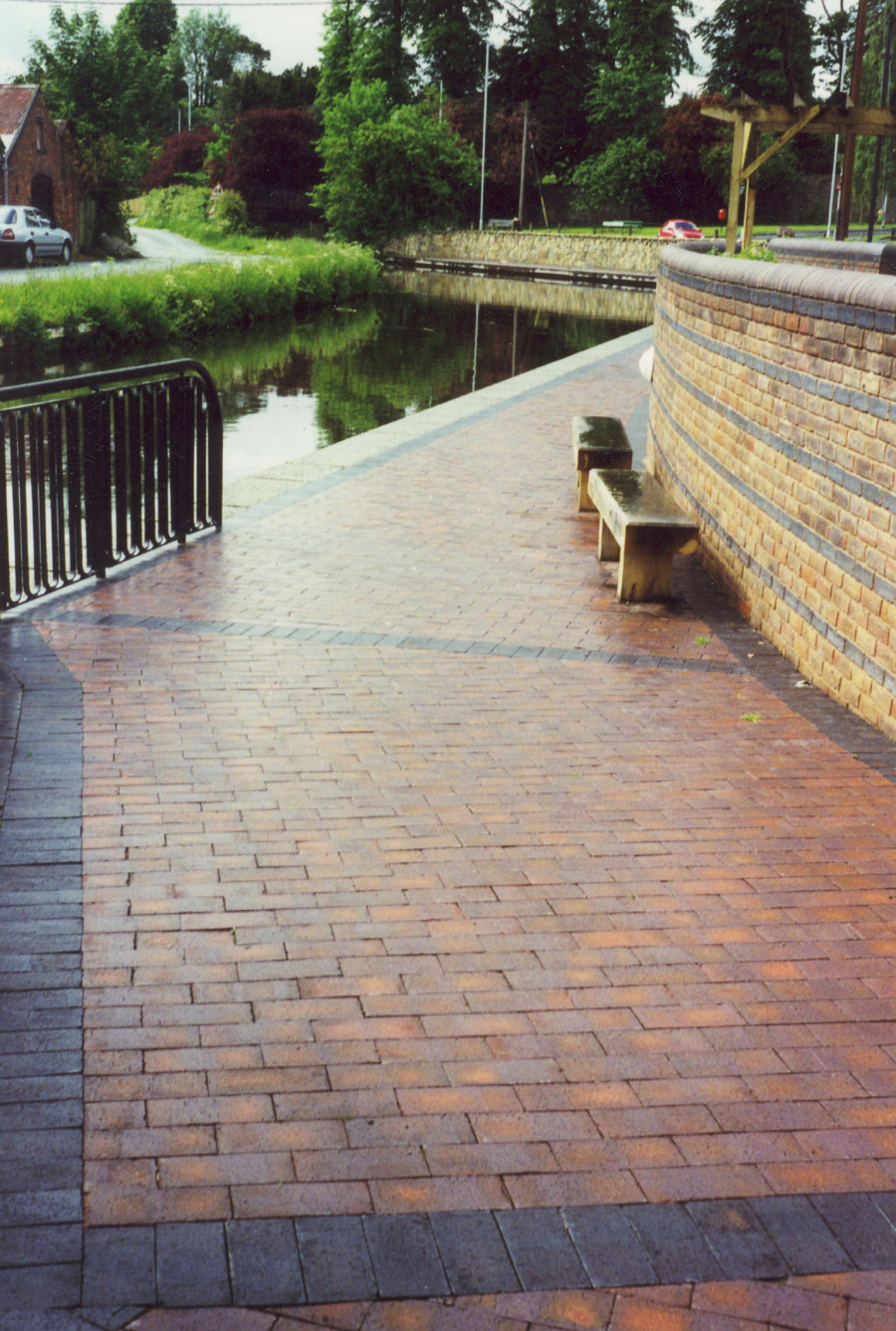
British Waterways
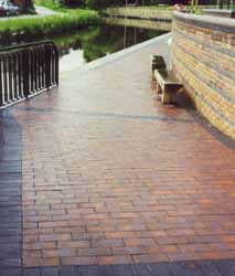
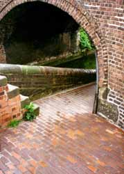
Ketley plain pavers were chosen in a joint redevelopment with Birmingham City Council of an area of Birmingham’s canal system, which subsequently became known as Canning Wharf, because of the ability of Ketley Brick to manufacture paving bricks of outdated dimensions of 10”x5” and 12”x6”. British Waterways were delighted with the appearance of these pavers and as a result generated a standard specification for Ketley brown brindle pavers to be used for all the quadrants where the lock gates are opened. This in turn led to paving large areas of towpath in the general refurbishment of the canalside in the urban environment. There are more miles of canal in Birmingham than there are in Venice, so this project became a major user of Ketley products especially during the 1990’s. This continues to this day when sections of the canal are ready for refurbishment, although nowadays this comes under the auspices of the Canal and Rivers Trust.
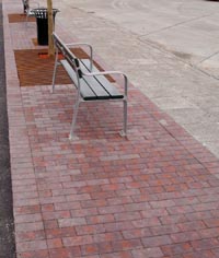
Paving in Napier, South Island, New Zealand
 copyA1.jpg)
Taradale Shopping Centre in Napier, South Island is a boutique shopping destination centred around a traditional busy high street. The planners at Napier Town Centre have traditionally sourced their paving materials from Australia, but having seen Ketley's blue square edged pavers, they decided the blue colour would add a unique feel to this up-market area. The planners could not find anything similar in Australia and therefore after setting up a test site of the pavers, they specified Ketley for the 3600m2 area. Full details
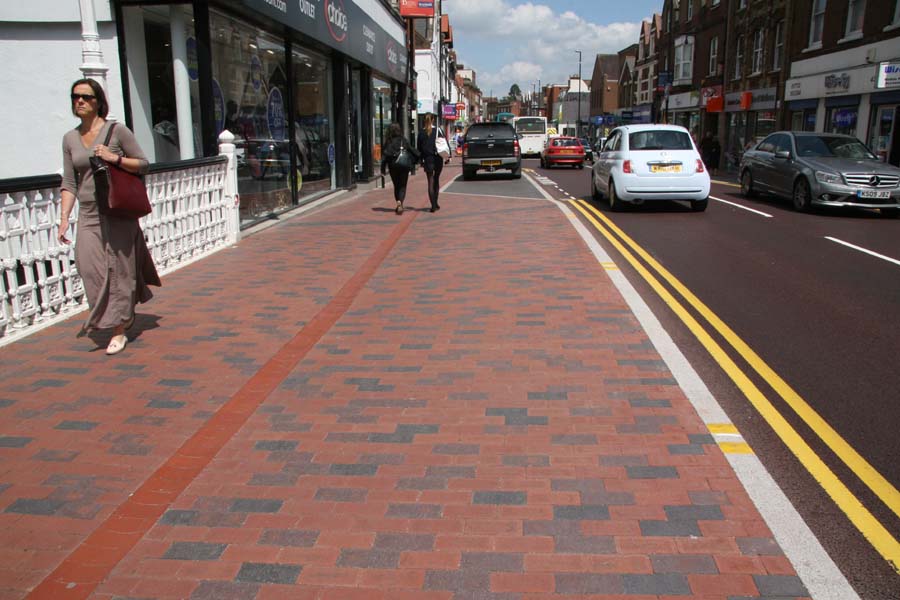
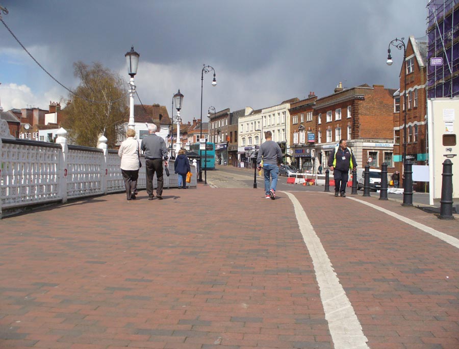
Tonbridge High Street
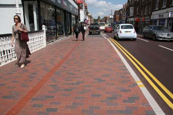
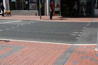
A regeneration project has been carried out in Tonbridge High Street by Amey Highways to improve the shopping experience by shifting priority from vehicles to pedestrians. A mix of 65% Red, 25% Brown Brindle and 10% Staffs Blue 'Classic' square edged Ketley pavers was chosen by Geoff Pearson, Conservation Officer at Tonbridge & Malling Borough Council to continue the tradition of using clay pavers for pavements in this area. Ketley’s tactile blister paving and blue corderoy paving have been used to demarcate the crossing area and the edge of the footway. The scheme, designed by Amey Consulting, has been a real success and Ketley pavers have played a significant role by enhancing the historic area, giving a welcoming look and feel to the High Street. Full details >>
Shelly's Hotel, Lewes
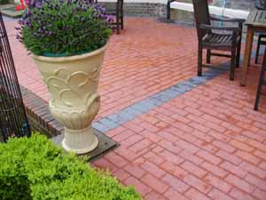
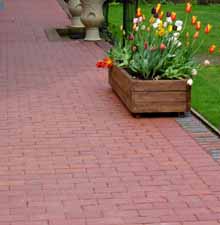
The Shelleys is a Grade II Star listed building in Lewes, built in 1577. Lewes is one of the best preserved small market towns in England and characterized by historic buildings and traditional building materials. Brick pavements in traditional Staffordshire Red are a feature in Lewes and these pavers were therefore a fitting choice for the restoration of this outdoor space. As the owner Mr Fernandez explains “They are a traditional product in a natural colour which complements the brickwork in the building. The red 'Classic' square edged pavers sit well with the red feature brickwork around the windows, and we have edged the terrace with the Ketley Staffordshire Blue paver which provides a good match to the main brickwork of the house.”
Environmental
Place of Manufacture: Brierley Hill, UK
Environmental Management: 14001 Download Certificate
Quality Management : 9001 Download Certificate
Download the Ketley Quality and Environmental Policy
Life Cycle: BRE Global Certification in accordance with EN 15804:2012 Download Certificate
Energy: Fired in gas kilns to 1130o C
Raw materials: Etruria marl clay from our own quarry in Cannock, 12 miles from our factory, and sand
Lifespan: Clay pavers are long life building products and Ketley's pavers are the toughest and most durable clay pavers you can buy.
Recyclability: Ketley clay pavers can be carefully lifted and reused. They can also be crushed and used as aggregate and/or as an inert bulk fill
Packaging: We keep packaging to a minimum using wooden pallets and we do not shrink wrap our paver packs.
Find out more about Ketley's approach to sustainability
Click for the Brick Development Association infographic on Sustainability of Brick
See below the latest video about Sustainability of Brick from the Brick Development Association
Tech Spec
Staffordshire 'Classic' pavers Specification Sheet
Performance Standard: BS EN 1344:2013
Ketley Staffordshire blue pavers are produced at our works located in the heart of the Black Country. They have been made from our own Etruria Marl since Victorian times. Their unrivalled physical properties include their strength, durability and permanence of colour.
|
Work Size mm |
Pattern |
Pack Weight |
No per pallet |
Units/m2 Rigid with 10mm joint |
Units/m2 Flexible butt Jointed (3mm joint) |
|
215x102.5x50 |
Square Edged |
1300kg |
500 |
40 |
44 |
|
215x102.5x65 |
Square Edged |
1320kg |
400 |
40 |
44 |
|
200x100x50 |
Square Edged |
1150kg |
500 |
43 |
48 |
|
200x100x65 |
Square Edged |
1200kg |
400 |
43 |
48 |
|
200x100x50 |
Chamfered |
1150kg |
500 |
43 |
48 |
|
200x100x65 |
Chamfered |
1200kg |
400 |
43 |
48 |
|
|
|
|
|
||
|
Colour |
Staffordshire blue, red, brown brindle or brown antique |
||||
|
Raw Material |
Etruria Marl Clay |
||||
|
Manufacture |
Extruded, Wirecut and fired above 1130 degrees C |
||||
|
Bulk Density |
2,300kg/m3 |
||||
|
Texture |
Dragfaced |
||||
|
Size, Tolerance |
BS EN 1344: 2013 |
||||
|
Size Range |
R1 |
||||
|
Mean Transverse Breaking Load |
T4 |
||||
|
Unpolished Slip/Skid Resistance |
U3 |
||||
|
Abrasion Resistance |
|
||||
|
Freeze/Thaw Resistance |
FP100 |
||||
Fittings
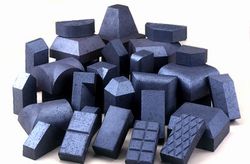 Ketley Brick have a long history producing special bricks and pavers.
View our Paver Specials Gallery
Browse our paver specials range online
Our unique plant produces a traditional natural clay colours for both the Paver and Brick ranges. Because our squares, pavers and specials are fired together, our colours are consistent through the range.
Ketley Brick also offers a made to measure service for bespoke requirements, this is covered in the Special Shapes section.
Laying
Paver Laying
Clay pavers should be laid in accordance with BS 7533-3:2005+A1:2009.
For post laying care, download our guide here
Download industry guidance on paver cleaning here
It is useful to plan the layout of pavers before full scale laying begins. It may help to minimize the number of pavers that need to be cut. It will help to identify the likely sand surcharge needed in setting levels. It will also indicate the likely finished appearance and the standard of on-site workmanship.
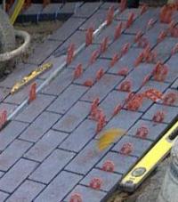 Clay pavers should be laid by hand, commencing from a straight starting edge on the prepared bedding course. They should be laid slightly open to provide a finished joint width between pavers of approx 2-5mm beyond the edge protection nibs to permit infill and to minimise damage in compaction and subsequent use. Failure to do this may result in chipping of the clay pavers.
Ketley pavers can be supplied with or without nibs. (Please note the nibs are there for edge protection of the pavers and are not spacer nibs, therefore the nibs should not be used to determine the gaps between pavers). If deviation from the bond pattern does occur, the pavers can be adjusted to open the Joints to about 5mm. This process is known as gapping. A small percentage outside this figure will not affect paver performance.
When a 90° herringbone bond pattern is used, a string line should be set up at right angles to the starting edge, and a "nose" of paving can then be advanced along it. When laying 45° herringbone pattern the laying face should develop parallel to the starting edge.
-
 Pavers should be selected from three or more packs to ensure a thorough mix. If stocks of new pavers have to be laid on new work, they should be stacked about one metre back from the leading laid edge.
 -
As far as possible whole pavers should be used. Pieces of less than 1/3rd of a full paver should be avoided. Various items in the Ketley range of paver fittings overcome this problem. Infilling of boundaries and obstructions should be completed before vibration commences. Paver cutting should be carried out by a disc cutter, not by the use of a splitting machine or hammer and chisel.
It is important to check the pattern of pavers against string lines as work progresses and adjust as necessary.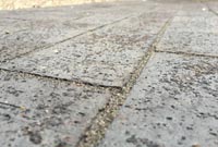
Once a sufficient area of clay pavers has been placed, approximately 40m2 on larger sites, fine dry sand should be brushed into the joints.
After brushing into the joints, surplus sand should be brushed away before compaction begins. Pavers should then be compacted into position by two or three passes of a vibrating plate compactor fitted with a neoprene pad. As recommended in BS7533-3:2005, the plate area should be at least 0.20m2. it should transmit an effective force of 50-75 :kn/m2 at a vibration frequency of between 60-1OOHz. Compaction should not be performed closer than one metre from any unrestrained edge.
 Further sand should then be applied and the procedure repeated. After final compaction 1-2mm of sand can be spread over the paved area to promote joint fitting and to fill any voids which may develop.
Commencement of use of the pavement may need to be delayed if the bedding course is saturated following heavy rain. During the early life of the pavement there is likely to be some settlement of sand within the joints. Therefore the site should be monitored and arrangements made for further sand to be brushed in, to top up the joints.
Instructions on how to lay for rigid construction can be found in our Clay Pavers and Fittings brochure (available here for download)
Cleaning
Paver Cleaning
Paved areas should be swept with a stiff brush on a regular basis, to remove dust and detritus that tends to accumulate, especially in sheltered corners, and around drains.
The paving should be inspected on a quarterly basis, looking for loose, damaged or stained paving, and checking that the joints are filled. Vacuum road sweepers should not be used during the early life of the pavement as they will remove the jointing sand. Other causes for loss of jointing sand include, erosion by exceptional surface water flow, the effects of high-powered engines or power-washers, action of ants or insects and loss due to movement of the paving.
In situations where an excessive amount of grime and dirt has built up, occasional steam cleaning should be carried out. Jointing sand levels should be checked after this operation and replaced as required.
Pavements in damp areas such as beneath trees and in permanent shade may develop unwanted weed or moss growth. Regular brushing will disrupt emerging weeds, a proprietary weed killer should be used which will have no detrimental effect on the pavers for more stubborn weeds. It is always wise to test the product to be used in a small area first.